Last updated on: September 5th, 2026 00:49 am
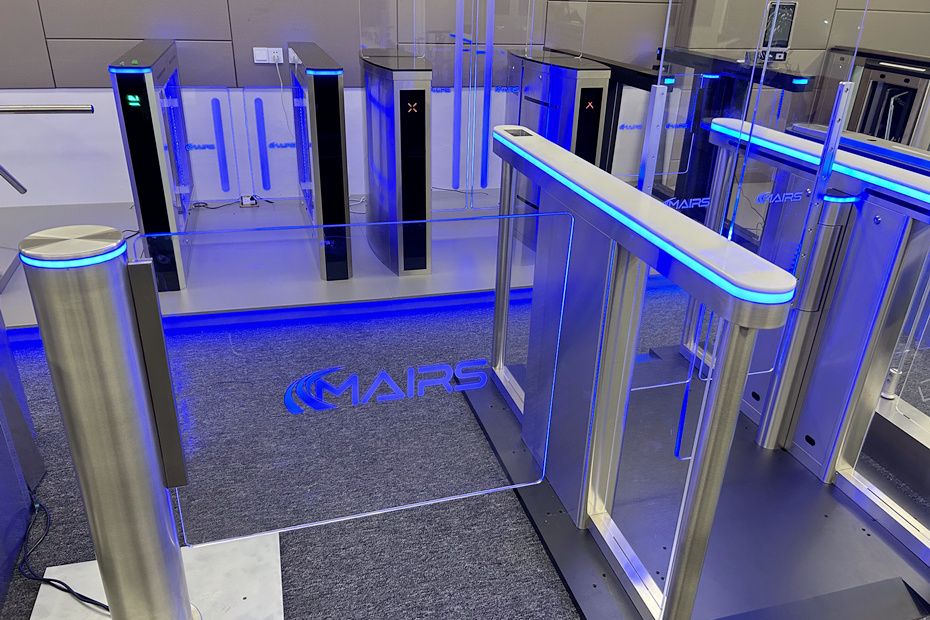
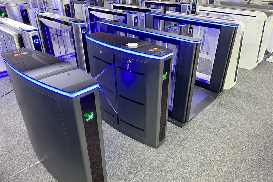
The overall process of sliding gate security turnstile installation is divided into six stages: preliminary survey preparation → ground wiring pre-embedding → sliding turnstile gate positioning and fixing → line wiring installation → machine function debugging → acceptance and completion, with tools, standards, and key points for avoiding pitfalls marked at each step.
Step1. Preliminary survey and preparation of materials and tools (completed 1 day before sliding turnstile installation)
1. On-site survey standards
Ground requirements: Concrete/marble solid ground, with a flatness error of ≤ 3mm/2 meters, and cannot be backfilled soil or hollow bricks; If the ground height difference is too large, a cement leveling cushion layer needs to be made first.
Channel size: The standard single-person channel is 600mm wide, and the accessible channel is ≥ 900mm; 15cm maintenance space is reserved on both sides of the sliding turnstile body, and a 1.5-meter buffer passage area is reserved in the front and back.
Outdoor special requirements: A 10- 20 cm cement base should be poured to lift the sliding turnstile gate, accompanied by a rainproof roof, and waterproof and lightning protection measures should be taken.
Power planning: A dedicated 220V circuit with a 30mA leakage protector, and it is prohibited to share the circuit with air conditioning and fitness equipment.
2. Tool List
Impact drill, 12mm drill bit, level, tape measure, marker pen, M12 stainless steel expansion bolt, complete set of hex wrenches, multimeter, wire stripping pliers, electrical tape, PVC conduit, zip ties, sealant.
3. Equipment inventory (unboxing verification)
Main/auxiliary unit translation switch, tempered glass translation baffle, motherboard controller, brushless servo motor, infrared anti-pinch grating, card swiping/facial recognition panel, power cord RVV3 × 1.5, Category 5e Ethernet cable, RS485 communication cable, ground wire, all screw accessories, instruction manual wiring diagram.
Step2. Ground slotting and pre-embedding of lines (foundation process, determining later aesthetics)
1. According to the placement position of the sliding turnstile gate, slot a groove in the center of the base, with a depth of ≥ 60mm for the wire groove. The wire conduit should be 50mm above the ground, and the pipe opening should be bent downward to prevent water ingress.
2. Installation of strong and weak current pipelines (the same pipeline is strictly prohibited)
-Strong current (power supply): RVV 3 × 1.5 power cord (fire L/zero N/ground PE), single channel separately wired;
-Weak current (signal): Category 5e Ethernet cable (main and auxiliary unit connection, face/card recognition), RS485 communication cable;
3. Reserve 1 meter of spare cable for each conduit, apply sealant to the conduit for dust and water prevention, and backfill the conduit with cement to level the ground.
4. All outdoor wiring uses metal galvanized conduit and adds waterproof joints.
Step3. Gate positioning, drilling, and fixing (core precision steps)
1. Benchmark positioning
Multiple sliding turnstile gates are installed side by side, with each turnstile security barrier gate selected as the reference. The gates are placed above the embedded conduit, aligned with the centerline of the channel, and marked with a marker pen on the 4-6 fixing screw holes of the base.
2. Remove the sliding turnstile gate and use an impact drill to drill holes vertically on the ground, with a diameter of 12mm and a depth of ≥ 70mm, and clean the dust inside the holes.
3. Reposition the sliding turnstile gate, align it with the hole, insert the M12 expansion bolt, and gently pre-tighten the nut (do not completely lock it, facilitate horizontal alignment).
4. Horizontal calibration: Place the level gauge around the base and fine-tune the gasket to ensure that the body is completely level. The height and front and rear end faces of the left and right gate machines are completely flush.
5. Multi-channel alignment standard: After the left and right translation baffles are closed, the gap is 3- 5 mm, and the left and right baffles are completely aligned without any height displacement.
6. After all alignment and calibration are completed, tighten all expansion screws one by one and shake the sliding turnstile gate firmly without looseness.
Step4. Internal wiring installation (full power-off operation, safety first)
1: Grounding priority (essential for preventing leakage)
The metal chassis shell, motor, and motherboard are all connected to protective grounding wires, which are uniformly connected to the building’s main grounding bar with a grounding resistance of ≤ 4 Ω.
2: Wiring the high-voltage power supply
The 220V power cord is connected to the motherboard power terminal, with strict correspondence between the L live wire, N neutral wire, and PE ground wire. The wiring terminal is tightly pressed, with no exposed copper wire, and insulated with electrical tape.
3: Host and secondary machine online communication
Dual machine linkage: 1 2-core wire connects the main and auxiliary boards of the sliding turnstile gate, and 1 3-core wire connects the main and auxiliary drive boards of the sliding turnstile gate.
4: Wiring of peripheral modules
1) Top card swiping/facial recognition panel: Ethernet cable connected to the motherboard recognition interface;
2) Infrared anti-pinch grating: The gratings on both sides of the left and right channels are connected to the anti-pinch terminals of the motherboard;
3) Emergency stop button and manual door opening button: The control line is connected to the IO terminal of the motherboard.
Wiring inspection
The multimeter detects that there is no short circuit or loose connection in the circuit, and all circuit ties are neatly stored inside the chassis without squeezing the motor track.
Step5. Whole machine power-on debugging (divided into three steps: no-load, single machine, and linkage)
1. Safety check before powering on
1) All lines have no short circuits and reliable grounding;
2) Manually push and pull the glass baffle, with no jamming or friction on the track;
3) There are no tools or screws left inside the chassis, and there is no debris in the movement area of the baffle.
2. No-load motor debugging (manual test with power off)
Manually push the translation baffle, confirm that the track is smooth and free of jamming, adjust the track limit buffer rubber block, and ensure that the door opening and closing buffer is soft and free of impact.
3. Power on single-machine debugging
1) Connect the 220V power supply, self-check the sliding turnstile gate, and the top LED indicator light is on normally;
2) Set the door opening and closing speed and delay closing time (default 3 seconds, adjustable as needed);
3) Test infrared anti-pinch: If the grating is blocked in the middle of the channel, the baffle will immediately stop and open in reverse;
4) Test mechanical anti-pinch: Gently push the running glass baffle, and the sliding turnstile gate will immediately stop for buffering.
4. Dual machine linkage and identification system joint debugging
1) Swipe card/face recognition, verify opening: After successful recognition, the left and right baffles will synchronously move and open;
2) Anti-tailgating test: One person swipes their card, two people enter at the same time, and the second person triggers the infrared sliding turnstile gate to close the alarm;
3) Reverse passage test: Reverse sliding turnstile gate breaking, gate locking, and audible and visual alarm;
4) Emergency stop test: Pressing the emergency stop button instantly locks the baffle and prevents it from moving.
5. Detail optimization
The baffle switch has no noise or impact, the LED traffic indicator light switches between red and green normally, and the alarm buzzer volume is moderate.
Step6. Cleaning, acceptance, delivery, and closure
1. Clean the dust and construction waste inside the chassis, wipe the stainless steel body, and the tempered glass baffle;
2. Lock the chassis door and apply sealant to all circuit openings;
3. Complete functional acceptance checklist verification: power supply stability, synchronous switch, dual anti-pinch, identification door opening, anti-tailgating, emergency stop, and sound and light alarm are all normal;
4. Delivery to customers: explain daily operations, emergency handling, simple troubleshooting, retain wiring drawings and equipment manuals
Key sliding turnstile installation points for avoiding pitfalls
1. Strong and weak electricity must be managed separately, as having the same management can cause facial recognition signal jamming and recognition failure;
2. Without grounding, there is a risk of electric leakage and shock, and it is necessary to strengthen grounding in damp places;
3. If the ground is uneven, fix the sliding turnstile gate directly, and if used for a long time, the baffle will shift, and the motor will wear out quickly;
4. Delivery is prohibited without debugging the anti-pinch function, which may lead to safety accidents caused by pinching people;
5. Outdoor turnstiles must not be directly placed on the ground, and the base must be raised to prevent rainwater from flowing back into the chassis and causing a short circuit.